
I mentioned briefly in my post about controlling LEDs with my Amazon Echo that I have some wireless outlet switches that I wanted to control. At the time I didn’t have a transmitter that could switch them on, and it didn’t really want to crack open the remote and mess with it. Weeks later, the transmitter that I’d ordered arrived. I didn’t have much opportunity to dive into it in the project until this weekend.
First off, there are a lot of people who have already done this. That kind of thing is nice because it means many of the difficult problems have been solved and I can get to doing the cool part. After poking around a bunch of posts and pages about similar projects. I found this instructable that provided a good approach to solving this problem.
The first thing you have to do with one of these is figure out what the signal is. The instructable suggested using connecting a matching receiver (315Mhz in this case) to an oscilloscope to listen in on the transmission going from the remote to the outlet. I had purchased an oscilloscope several years ago but it never got a lot of use – I didn’t know really how to use it. Over the past couple of years I’ve stumbled across tips and tricks about O-scopes and found myself finally able to use that knowledge. Once I connected the receiver up, I pressed one of the buttons on my remote and got the following:
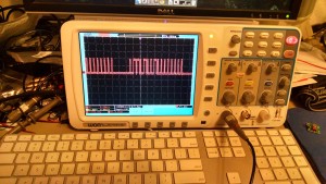
This waveform is the signal being picked up. It’s happening a few times and I stopped my scope on one of them. This waveform is voltages – 0 volts for low, 5 volts for high. We care about the length of the high values. Some are short, some are long. Because we’re trying to read this like a computer would, we’ll use binary. Short pulses can be mapped to “0”, long pulses mapped to “1”. This particular signal looks like this (broken into 4 bit groups):
0110 1001 0000 0000
As soon as I captured that first signal, I pressed all the other buttons to figure out what they were. Here are the 3 “on” button signals:
0110 1000 1000 0000
0110 1000 0010 0000
0110 1001 0000 0000
The first thing to notice about these the 4 bits in the front and the 4 in the back. They’re identical, which means they probably act as some sort of flag for the receiver “beginning” and “end” – so the stuff in the middle is what we really care about. Those 8 bits in the middle are the specific signal for a given channel.
The next thing we need to do, is replicate it and the trick to that is going to be timing. We need to know whether something should be read as a “1” or a “0”. The way we do this is count how long the signal was high.
Going back to the oscilloscope, I measured the times when the signal changed, and did the math to figure out the gaps. Turns out my scope has a way to capture the screen. I wasn’t able to find it from the menu, but I was able to access it over the network.
Here you can see the position of the purple cursors. First on the big gap before the waveform, then on each change in voltage. In the following, us refers to microseconds:
600us high + 1800us low = 2400us // off or 0
1800us high + 600us low = 2400us // on or 1
Now I know how long each bit is going to be in my signal, and I can start writing some code. You can find the code I wrote in Gist, but here are a few highlights:
#define HIGH_TIME_LONG 1800
#define LOW_TIME_LONG 600
// Off, or 0
#define HIGH_TIME_SHORT 600
#define LOW_TIME_SHORT 1800
Here are the two values that describe high and low for my outlets. They’re used in the two functions the output the signal
void bit_long()
{
 digitalWrite(transmit_pin,HIGH);
 delayMicroseconds(HIGH_TIME_LONG);
 digitalWrite(transmit_pin,LOW);
 delayMicroseconds(LOW_TIME_LONG);
}

void bit_short()
{
 digitalWrite(transmit_pin,HIGH);
 delayMicroseconds(HIGH_TIME_SHORT);
 digitalWrite(transmit_pin,LOW);
 delayMicroseconds(LOW_TIME_SHORT);
}
I also have two functions that describe the opening and closing strings:
//The common beginning 4 bits: 0110
void opening(){
 bit_short();
 bit_long();
 bit_long();
 bit_short();
}

//The common ending 4 bits: 0000
void closing(){
 bit_short();
 bit_short();
 bit_short();
 bit_short();
}
And lastly, here’s what turning a channel on looks like:
void ch1on(){
 for(int i = 0; i < 3; i++){
 delay(10);
 opening();
 bit_long();
 bit_short();
 bit_short();
 bit_short();

 bit_long();
 bit_short();
 bit_short();
 bit_short();
 closing();
 }
}
Essentially, We’re just toggling the signal up and down for a specific period of time. The loop is there because the first signal may not be “heard”. So we send it a few times to to make sure. The circuit was the easy part
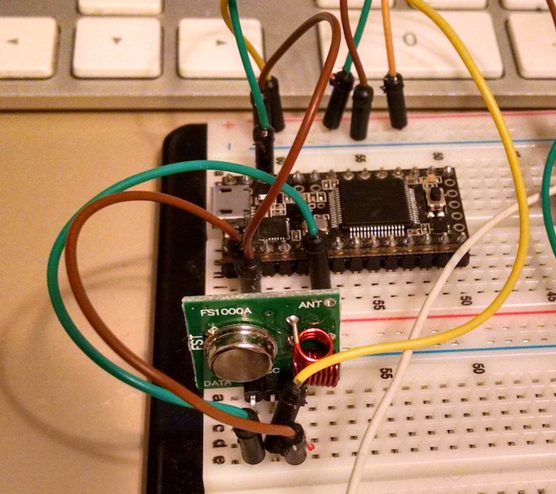
A Teensy 3.0, and a wireless transmitter. The transmitter only has a data input, so I didn’t need to bother with level shifting (it seemed to be fine with 3.3v as an input)
Now, the big question is “Did it all work?” Yes! The following video is not awesome because the camera on my phone doesn’t like quick changes in light, but it does show how this all works. In this particular code I have the lights switching on an off. Because of some timer issues I haven’t resolved they don’t quite turn on and off simultaneously.
It was a fun little project. The next thing I hope to do with this is pull it out of the Teensy circuit and connect it to an ESP8266 – a wifi chip. That way I can control it directly over the network, it can even serve its own web page!
This is just too cool. I’ve been trying to make a O-Scope from an Arduino. I’m looking at doing this with the remote for my fan in my room. I think it uses the same RF. More stuff for Alexa to run.