Sometime in 2016 I came up with an idea for a project: A Christmas ornament that counted the number of days, hours, minutes, and seconds until Christmas. But I wanted it to be nerdy and interesting, and something that I hadn’t seen anywhere else. So I started working on an ornament that would count down to Christmas in Binary.
Having finally gotten a working version after 6 years of effort, the most distinguishing thing about this project might just be all that it’s taken to get here. And while the technical details are, I’m sure, quite fascinating to many of you the story of doing all of this might be more interesting.
When I was younger, we would occasionally drive up a few hours to stay for a weekend with my Aunt and Uncle. I ended up in a little nook in the front of their house where they had a variety of things including a weird box with flashing red lights. I didn’t understand what this thing was, but enjoyed watching it. My uncle eventually explained to me that it was a binary clock, and I was absolutely delighted by it. Since I got into electronics, I’ve wanted to replicate that clock, but I didn’t have the know-how.
I’ve learned all kinds of things over the years about electronics and circuit design. I’ve applied those things to Christmas Countdown. I’ve also made lots of mistakes with the various versions of Christmas Countdown that have taught me about circuit design, using KiCAD, electronics fundamentals, etc. In many ways Christmas Countdown has been my white whale. If you can imagine for a moment that chasing Moby Dick made Captain Ahab a better sailor. Also unlike the white whale, this project didn’t kill me.
Initial ideas
My clock used Binary Coded Decimal – this means whenever you have a set of binary indicators for each position in a number. This was a bit more complex than I wanted. Initially I wanted to do 4 rows of lights. One for each day, hour, minute and second. I needed to represent at least the number 59 (seconds and minutes) which meant 6 bits (lights I could turn on for ‘1’ and off for ‘0’) for each row. That was a total of 24 LEDs. On top of that, I needed inputs for a couple of buttons – so you could set the time. 26 GPIOs. That is a stretch for any microcontroller. My solution was to use two rows of LEDs, and an indicator for Days/Hours and Minutes/Seconds. I could use just 14 GPIOs for LEDs and 2 buttons. 16 GPIOs is a lot, but not impossible.

Part of my original idea was to plug into an existing strand of Christmas lights, the same way my 1995 Star Trek Voyager Hallmark Christmas ornament did. It turns that in 2016 (and subsequently, 2022) Christmas lights are by no means universal. The bulb plugs are similar, but not compatible. Also, most Christmas lights are 120v for incandescent bulbs, or 5v stepped down for LEDs. The latter was something I could work with, but if I wanted 120v I’d need to include a transformer and also some sort of plug that would connect into any number of sockets.
Version 1 (Early December 2016)
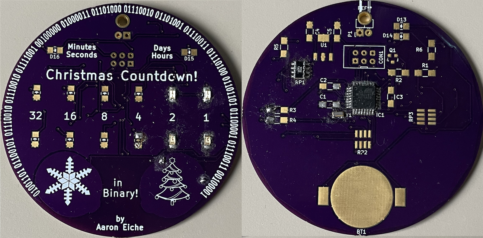
For some reason, I thought capacitive buttons were a really cool idea, I probably thought I could save a Buck on the BOM. Also, I really liked the look of a bare PCB and thought it’d be a good fit. PCB art had just started to be a thing (or at least a thing I was aware of.) So version 1 used an ATMega328, a few resistor arrays, and a battery that would provide power when the ornament was unplugged. I recall spending a lot of time trying to figure out a circuit to turn on the battery fail-over when power got cut. Also – the capacitive sense felt very out of my league.
It’s been so long that I don’t recall quite what didn’t work about it. I think I got the programming lines wrong so I couldn’t even get it to program. I remember though coming up with instructions to “Press and hold the snowflake for 3 seconds” I did eventually figure out how to do capacitive touch, but also found that it was unreliable because when pressing the button with your finger, you almost certainly have another finger behind the button, changing it’s capacitance. So it was really difficult to figure out how to tell what was a button press, and what wasn’t.
Version 2 (Early October 2019)
The second version I made ditched the capacitive buttons, added an LED driver chip (so I wasn’t dedicating the GPIOs to driving LEDs) and a battery backed-up Real-time-clock.
As I recall, this version didn’t work because I messed up the lines for the crystal. It was a strange, 4-pad component, and I’d laid it out wrong.
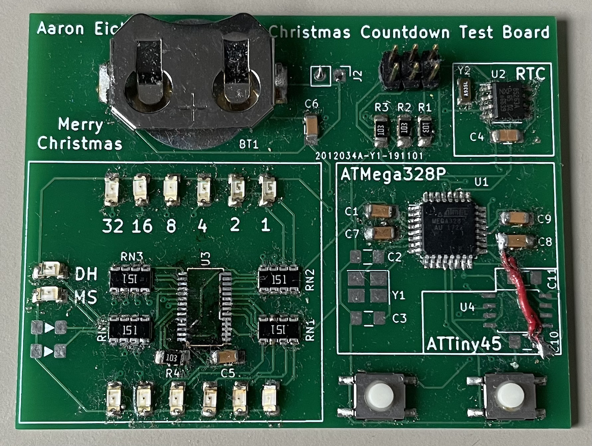
Version 3 Test (November 2019)
Frustrated with the failure of the second attempt, I decided to make proof of functionality circuit. In part this would be so I could poke at various pins while also seeing the lights changing. It fixed problems in v2, but of course had problems of its own. If nothing else, you can see very clearly the red ‘jumper’ wire between one of the capacitors and what I believe is a ground pad. The LED driver is also not on this board because I had the footprint wrong. This also marks the appearance of an additional footprint, for an ATTiny45. I realized that because I had the RTC and the LED Driver, and both used I2C, I probably didn’t need the Mega328. So I added the footprint hoping it would work out.
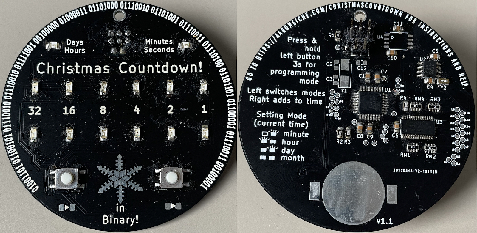
Version 3 (Late November 2019)
Version 3 attempted to fix the problems in the Test board, but tragically also did not work.
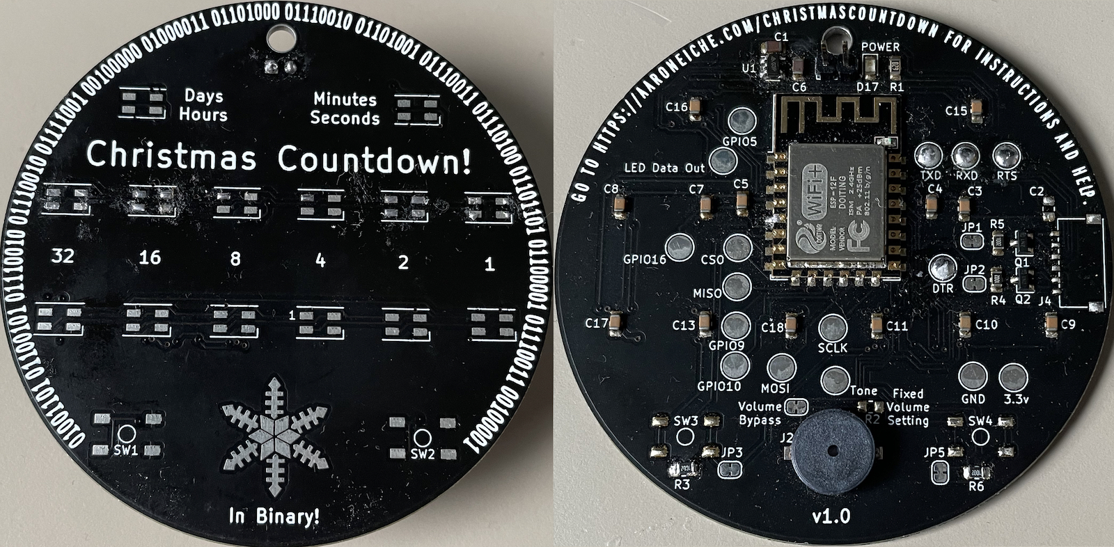
Version 4 (October 2020)
Sometime after version 3 I came across this video by Sean Hodgins. His ornaments in this case used an ESP8266 – a very popular 32 bit microcontroller that also had Wifi. It also used WS2812 LEDs – famously known as “NeoPixels”. These were advantageous not only because they could do RGB color, but because they were serialized. You could control all of them with a single IO line. I also read an interview with Brian Lough where he said regarding choosing a microcontroller “I ask myself if there’s any reason not to use an ESP8266“. The 8266 was clearly overspec’d for what I wanted to do, but I wasn’t trying to win an award for computing simplicity. So I built this version with an 8266 (specifically an AI Thinker ESP-12E) and RGB LEDs.
This one ditched the RTC. I figured I would just have it connect to the network, get the current time from an NTP server, and then display it appropriately.
This one was so close. I mentioned in a previous blog post that I would turn it on and it would heat up like a stovetop. It turns out I’d used the wrong footprint for the LEDs (I had SK6812s, and used the footprint for the WS2812b) – and it was directly connecting the GND to the Voltage. Beyond that, it pretty much worked. I randomly threw in a Piezo buzzer because I liked the way that Sean’s played Christmas tunes.
Version 4.5? (March 2021)
My receipts tell me there’s another version here, but I can’t find it. Suffice to say, that one also did not work.
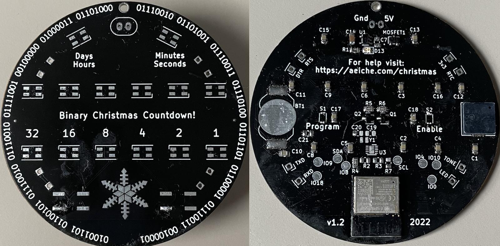
Version 5 (October 2022)
Having taken a break from the project for a bit, I started over from scratch. By this time Espressif (the manufacturer of the ESP8266) had started shipping the ESP32-C3. A new chip that replaced the 8266. It had Bluetooth too! I almost went with a drop-in replacement for the 8266 module, but decided to try my hand at a new thing. I re-added the RTC thinking that some people would want the “Paranoid version” where they don’t want to connect something to the Wifi Network. Also I learned about using a P-channel Mosfet for circuit protection. The voltage drop is virtually non-existent compared with a Schottky diode.
This version brought a new challenge. Supply chains for electronic components were stretched thin, and all kinds of things were suddenly unavailable. For this project, my preferred voltage regulator disappeared. I liked it because of its size and current supply capability. Some friends in my local electronics group suggested that there were lots of options to replace it, so I just started looking around for something about the same size that did the same job.
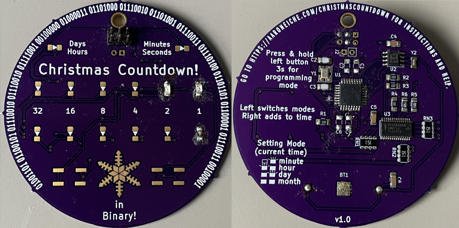
Once again, this version nearly worked. Like so many times before, I failed to actually check my footprints before sending the board off. I wired the RTC footprint very wrong. I assigned pins in the layout for the SOIC package, to the ATL package. Even though that was the only mistake, I struggled for a really long time to be able to program this. After a lot of experimentation, I realized that two of my pins had bridged and needed to reflow. I also did not include some recommended reset circuitry. This prevented the chip from restarting properly when you wanted to program it. Lastly, I chose some teeny-tiny buttons for reset and programming. I heard about them from Scott Bezek’s Nintendo Switch Ornament, and I thought they were perfect for my use case. They’re cool buttons, but they were a pain to press without some sort of plunger (the thing you press on), and that made them pretty useless.
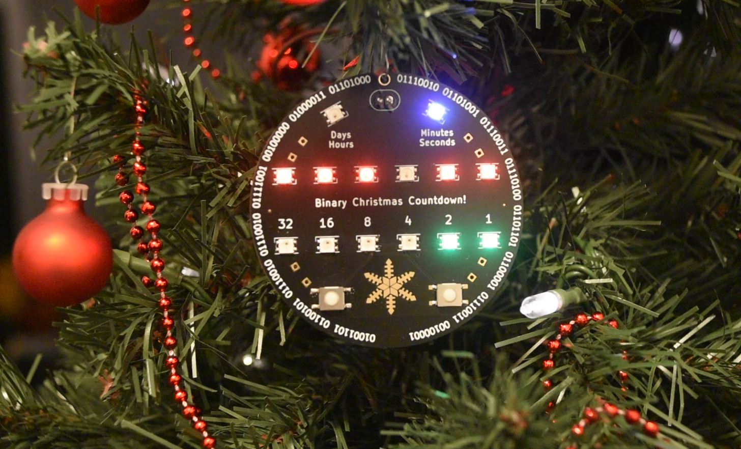
Success! Version 6
6 years later, and I have a version that works. Everything works. The RTC Works, the chip works, the LEDs work. I can plug this into a 5v power supply and it will count down to Christmas and display the “Christmas day” animation.

Lessons Learned
Okay – so to make this took me six years and hundreds of dollars of parts, shipping costs, blows to morale, etc. What did I learn in all this? I mean, besides how to use an EDA (KiCAD), how to source parts, circuit-design gotchas, how to read a datasheet… Well, here’s a couple:
- Always check your footprints
Check that your signals are what you expect them to be. Check that the part you have actually exists. Check that you can buy that part at a reasonable price. Check that the pin layout is what you expect it to be. Then check again. - Read the Datasheet
Know the recommended implementation. Manufacturers want you to have a good time with their product. Engineers have spent hundreds of hours testing and documenting their components to make it easier to use. Datasheets have tons of useful information that can help you. - Write down what you learned/what went wrong.
As I was writing this, I found I’d forgotten a lot of what went wrong with boards I’d designed. Fortunately, I wrote down stuff in my journal (which I keep on my computer) and have been able to search and find out what various things went wrong. It’s been quite the boon. I also have the circuit schematics and PCB layouts for each one. - Don’t make a product, but design as though you are
I have a bad habit of looking at all kinds of things as potential business opportunities. Early on I got really excited about making Christmas Countdown into a product. This added a dimension of stress that I didn’t need, and my view of the project became much easier when I set that aside. What has been useful is trying to understand the project from a product standpoint. Answering questions like “Can I make the BOM cheaper?” and “How can I program and test this quickly and easily?” It made me look at how to build a programming jig, and what a pick and place solution looks like. That part was really fun.
What now?
One of the strange things about getting it all to work is I’m a little uncertain on what to do next. There are improvements to be made to this board. When I was making the changes to the previous version, I almost made some bigger leaps, but I decided to correct just the things I knew were wrong. Here are a few of the changes I’d make:
- When I moved to the ESP8266 (and the ESP32-C3) I thought I could put a webpage onto the device. You could change settings, and setup NTP Sync, so the ornament would just get the current time. I still want to do that, but I wanted to get the project out the door. Also, those features make for a good incentive feature for a kickstarter, right?
- One of the buttons on the front (for choosing the mode and setting the time) is tied to pins for a USB port. I didn’t bother with the port, but it turns out that it’s not just for USB but also JTAG – which would have been an easy way to debug.
- The 2.54mm pitch Power supply is not my favorite thing. I think I want to replace it with a JST plug.
- Associated with the first point, programming the board is a pain. I added through-holes to use for Pogo-pins, but I realized that if anyone else uses the design, they may not have or want a pogo-pin programmer – they might just want a simple cable. A USB port would have made it super easy.
- The ESP32-C3-Mini-1 – the module on the board – is kind of a pain. It’s pads are all under the module. There is a slightly larger module – the ESP32-C3-WROOM-02 is a bit wider, but has castellated pads, which are hand solderable, and easily probably with a multimeter or scope probe. As of this writing, it’s 11 cents more expensive than the mini-1. I could also just use the bare ESP-32 chip and supporting components.
I don’t know if I’m going to pursue this any further. I might do a Kickstarter to make a bunch some day, or sell it on Tindie or something. I think it’s a really cool project and I’m really happy to finally have one in my hands. I don’t think I want to turn it into a business. I am interested in the things that I might do if I had make a hundred of them or something like that.
I want one!
I’m flattered. Thanks for thinking something I made is cool. If you’re not interested in ordering the PCB, and parts, reflowing solder, programming the chip, etc, I made a simple form put your email address into this form, and I’ll let you know when I get closer to actually making these things.
If you are interested in making one yourself, you can find the KiCad project, Schematic, PCB, Gerber files, and firmware all at in the Github repository. If you have questions, feel free to shoot me an email.
Thanks for reading through this adventure of 6 years of project stress. Merry Christmas, and Happy New Year.
*I’m pretty sure I had at least one idea about an ornament that just displayed the time on 7-segment digits. That was a challenge for me, trying to figure out how to set 4+ digits (28 pins -that’s 4 shift registers). Also the 7-segment components I was familiar with were all pretty thick. I didn’t think the aesthetic would work.