
As I mentioned previously, I have been getting more interested in creating props for my light shows. Part of that is because owning a 3D Printer allows me to experiment with shapes that are challenging to make it other ways.
I’ve been really interested in what I call snowballs – there’s spheres that have lights coming out of them in all directions. I’ve seen a few about in various states. We had a traditional Christmas light Sphere on top of our tree a few years ago that was manufactured by GE. Since last year I’ve been trying to come up with a design that would house a full strand of 50 nodes in a relatively small package. I am a dedicated FreeCAD advocate, but this one stretched my design chops a bit though.
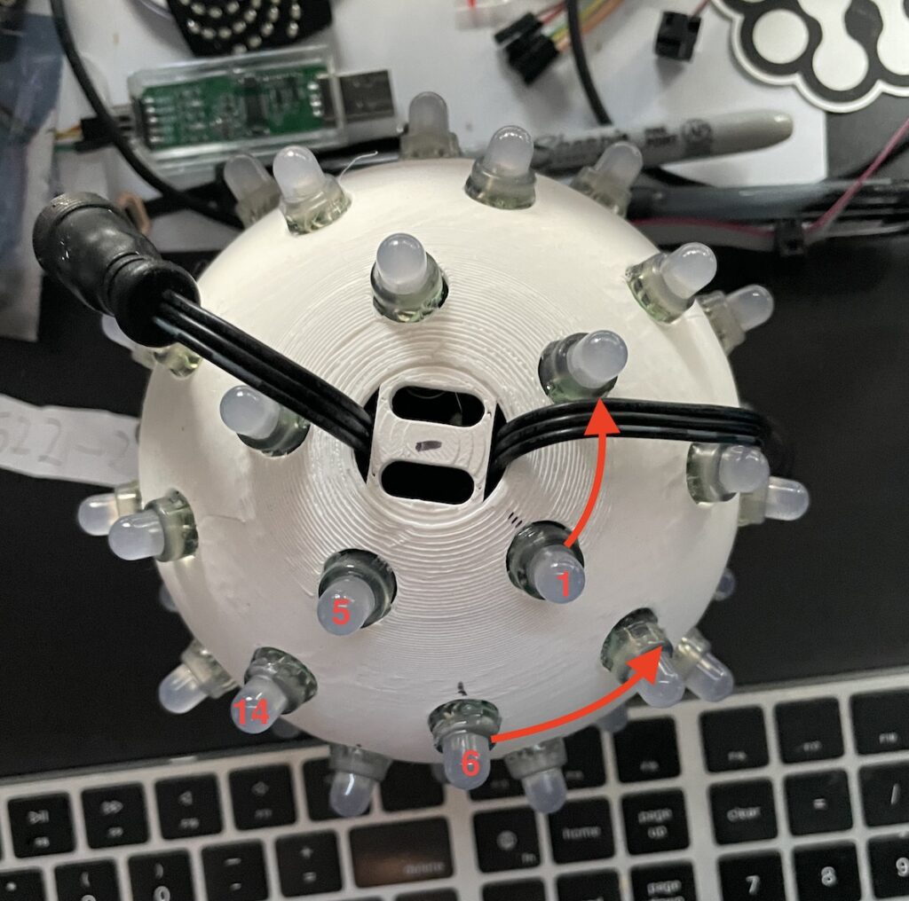
All 50 nodes, evenly spaced.
These “bullet” style RGB LED nodes typically come in 50 node lengths. I didn’t want to lose any of those precious pixels, so I set out to design a globe that would accommodate all 50. Beyond that, I wanted the layout to have lights distributed across the surface. Not just in lines going down. Additionally, I liked the idea of having two identical halves that I could assemble, and not an explicit top and bottom.
The combination I came up with was a row of 5, a row of 9, and a row of 11, then the same three rows in the reverse order.
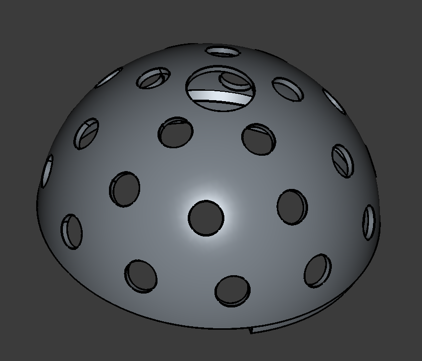
I divided up the available space across the sphere to make room for the nodes and spent a lot of time in FreeCAD learning about Datum Planes. A Datum Plane (singular of Data) just a flat thing you can put in space to draw from. I needed to draw a circle to push through my half-sphere at a given angle.

In order to make the two halves sit together properly, I introduced an inside rim around half the inside of the shell. When the two pieces went together, they complemented each other. This helped with alignment and just holding the whole thing together.
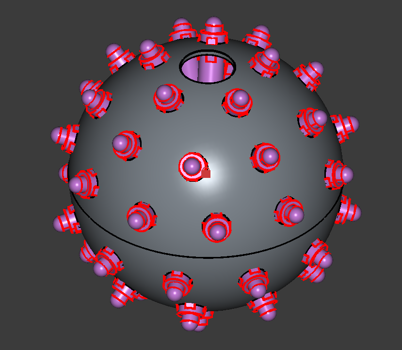
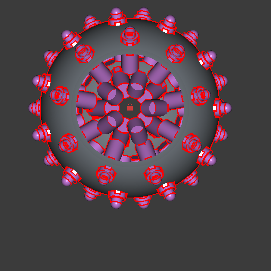
Finally, since version 1.0 FreeCAD has shipped with a built-in assembly tool, so you can actually see how everything goes together. This was a good way for me to see if everything worked. I didn’t see a model of one anywhere, so I made a little bullet node and put 50 of those in my model as well.
Printing
I printed these, and unfortunately they just required a lot of support. There really wasn’t any way around it. I did try with traditional (rectangular) supports and found that they didn’t really offer any more benefit over tree supports. I also attempted to print the spheres from the middle, but found that the middle seam suffered and the quality gain on the top wasn’t worth the effort.

How do I actually put this in the show?
I got the design dialed in pretty well. I was happy with how it was laid out, how the nodes fit and the printing (mostly). I printed and assembled 4 of these. I was set. And then I opened XLights and realized I had no idea how I was going to turn these props into actual, light-up elements in a show.
Xlights has a sphere model built-in, but it makes some specific assumptions about how the sphere is constructed. It assumes strands of lights going from the top to the bottom, and a number of strands. Basically the same number of lights in each column. My sphere was a mess compared to that.
The custom model layout tools are primarily thought of as 2D, or 2.5D at best. After all, most light shows are seen from the front. You’re given a grid where you can position your nodes and can place a picture behind the grid for help.

My sphere didn’t have a “front”, and even if it did, it was very challenging to orient. It was very hard to determine where the node tips were and I didn’t have an easy way to see the nodes “in the back”
After attempting to vibe code a script for FreeCAD that would export the node positions into an XLights model, I reached out to the Xlights subreddit for advice. Reading through it, a couple of things struck me which now seem obvious.
- I can build the model from the top down and just rotate it in my layout. Xlights doesn’t care what you think of as the “top” and it doesn’t care if you point your lights in a weird direction.
- By putting a clipping plane on the model, I could cut “slices” in the model and use those as a reference for placing the lights.
Once I got the model built, I gave it a test run and it worked! Even better, I put multiple models in the layout and tried with some group effects.
If you’re interested in printing your own, you can find the files right here, or also at Printables.com