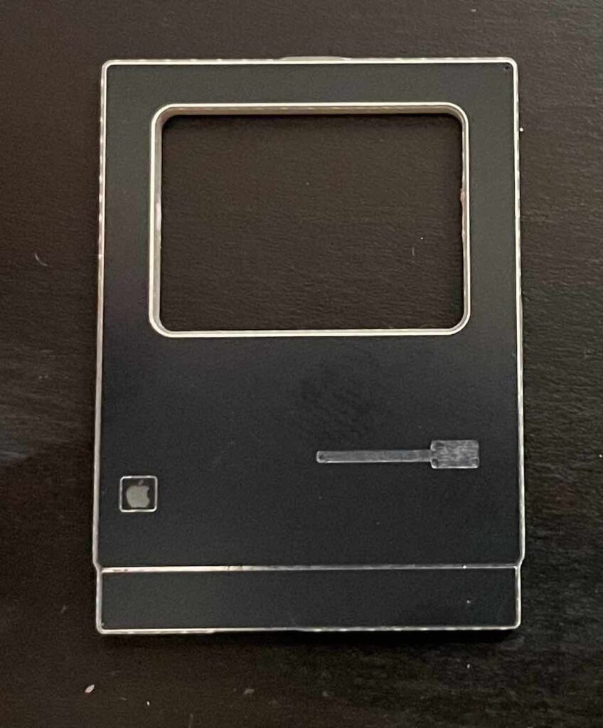
My second test run (version 1.1) showed up in the mail today. Version 1.1 fixes and moves the SAO connector to the center, adds an EEPROM and an LED behind the Apple logo (thanks for the idea Tom!). The EEPROM and LED are still coming in the mail.
One of the challenges I’m facing is how to attach the display to the main board. Because real-estate on the board is so tight, a typical surface mount header wouldn’t work. I didn’t want a through-hole header because I wanted the front of the SAO smooth.
The weird solution I’d come up with was to cut short lengths of copper wire and solder them to the pads on the back. It required desoldering the headers already on the board (and clearing the holes), sliding through the copper wire, bending them to the right position, and soldering in place.
I tried this a couple of times and in both cases, I accidentally ripped a pad off while bending the wire. This wasn’t looking good. I have a few more test boards, and some extra displays to experiment with, but I didn’t want to start losing parts to a hare-brained scheme.
Looking at the displays I’d bought – which again, had headers soldered in place already – I wondered if I could get away with just soldering the pins to the pads and just letting the surface tension wick the solder across the gap. As it turns out that solution worked really well, and is far easier to do.
I proved the concept using the board I’d already damaged
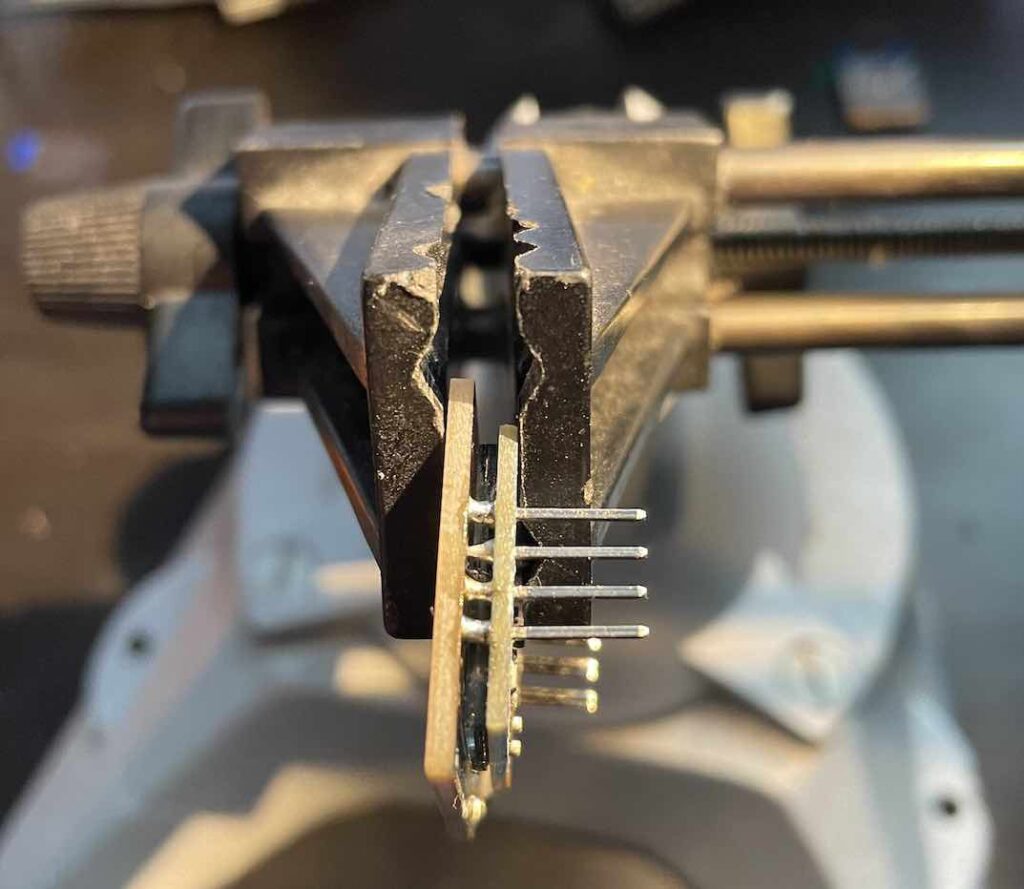
It’s a tight spot to solder in, but the included tip of my PINEcil did it without issue The solder pad and pins do the real work. When I actually get to assembling en masse, I think I’ll design a 3D-printed jig to properly position the display and the board relative to each other.
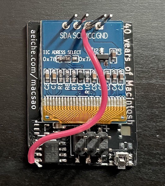
Of course, given the pad I ripped away, I had to hack together a solution. Fortunately the contacts were easy to reach. When the EEPROM and LED show up, It’ll take a little effort to get them soldered in place.
I’m pleased to say that my software uploaded without issue on the first try. It even runs on last year’s VectorScope badge. I was a bit surprised at this because I put rechargeable batteries in which are nominally 1.2v. The datasheet of the CH32V003 said that it wanted a 2.7v minimum. My multimeter tells me that the battery output of the SAO port is currently at 2.65v (that’s freshly charged.) I’ll have to see how long it can operate at that.
There has been a bit of scuttle on the Hackaday discord about the startup state of this year’s badge GPIOs. If you have the pin plugged into the SAO header, it may trigger programming mode. (Specifically, it was Tom Nardi’s Cyberdeck SAO with the ATTiny3224, but I believe the CH32V003 basically uses the same protocol.)
I have a board version in KiCad right now that adds a jumper for enabling programming via the header. With that, instead of bridging it with solder I would add a pogo pin to my programming setup and just have it connected which inserted.
I’m this close to being locked in on the hardware. Firmware is coming along. I’m working on the EEPROM storing and retrieving sequences.