
PCBs Arrive!
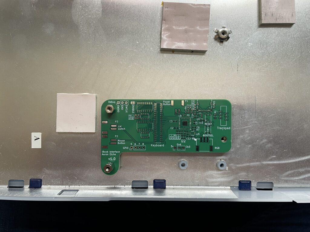
The PCBs arrived conveniently this week a little earlier than I expected. I didn’t have time right away to assemble one, but I did pop one into the chassis to do a test fit. The right-side bolt is a little offset, but not enough to prevent it from being screwed into place securely.
Assembly
I ran into two problems when trying to do assembly. First, I did not order a solder paste stencil. At the time I thought I could use a paste-pump device that I purchased and thought would work really well. It probably could, but it turned out to be quite a lot more work than I wanted it to be.
Second, I was missing parts that I needed! I thought I’d got everything in my Digikey order, but apparently missed a few things. Most important was the shift registers. And it turned out the resistor networks I used for pull-downs on the shift-register lines were the wrong size. I was looking for a resistor network that was equivalent to four 1202-sized resistors (A 2012 RN). instead, I got an RN that was four resistors in a 1202-size package.
Reflow and re-reflow
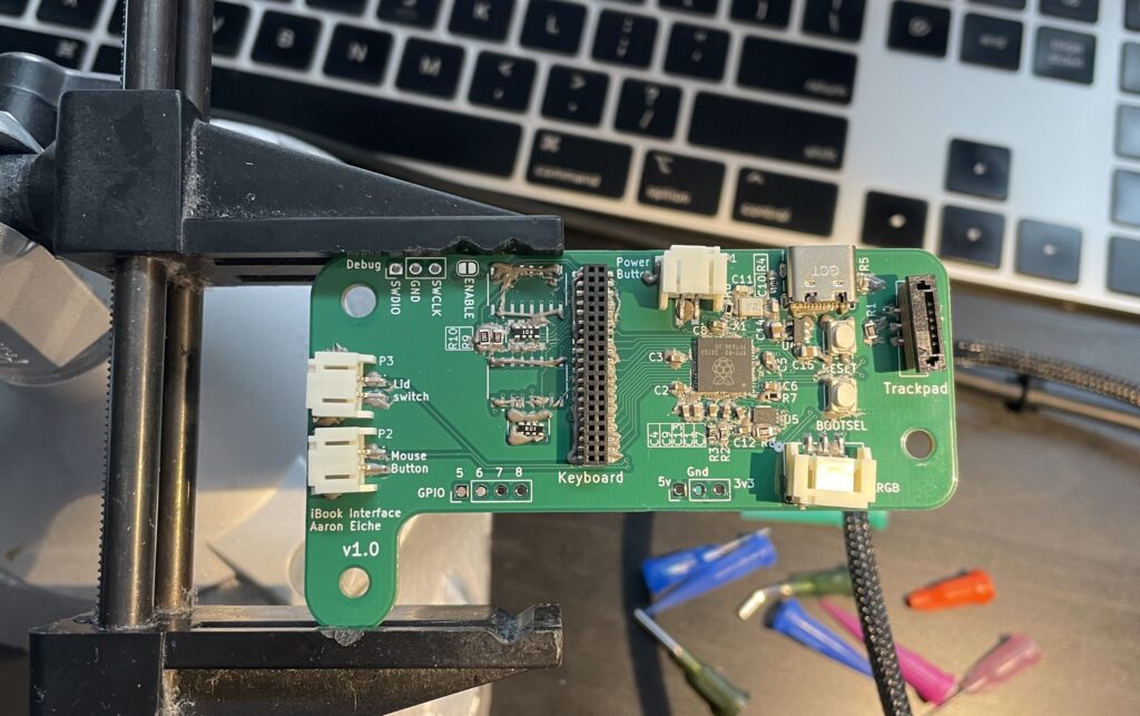
My first attempt at reflowing the board wasn’t great. Lots of solder bridges, and a few components misaligned. Worse yet, the paste hadn’t flowed uniformly across the board, so some components weren’t reflowed at all. I tried to correct the issue with some judicious hand-soldering, but without much luck.
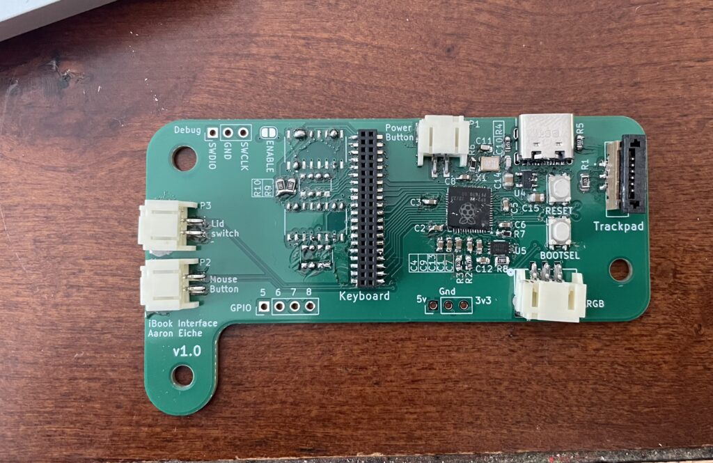
Trying to plug in the board revealed another design-flaw: There were no indicators for power or anything else. I had nothing to let me know the board was working. I hadn’t added any LEDs because I didn’t actually want LEDs in the case making light in weird spots. In retrospect some test-points and some optional LEDs would probably save me from a fair bit of effort.
Fortunately, I have a hot-air rework station. This blows hot air and can be used to make solder flow in targeted ways. Hot air reflows the solder, the solder wicks to the pads and the components self-align.
After doing some repair, things improved – I had power, both on the 5v and 3v3 lines. I replaced the RP2040 because I wasn’t seeing the 1v1 line it provides internally. I’m willing to bet that I put too much heat on the whole thing and damaged something. The second time worked… better, but I still didn’t see anything when plugged in.
Lessons learned
After my first attempt, I went an ordered a solder-paste stencil. I ordered it from oshstencils.com. It’s definitely paying a premium over having ordered it from JLCPCB when I ordered the boards, but worth it.
After I get the missing parts I’m going to properly stencil the board, and do my best to run the reflow curve. Then we’ll try this all again.