Having successfully proven my circuit with a hand-wired board, I’ve pursued a printed circuit board.
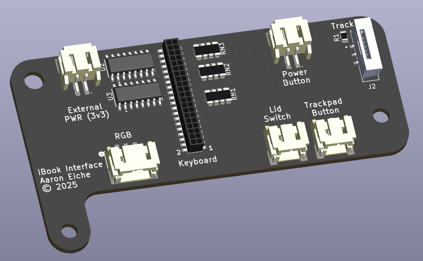
A few more things have been added to the circuit since I got the keyboard and trackpad working. Specifically, inputs for
- The Trackpad button
- The Power button
- The Lid-closed sensor
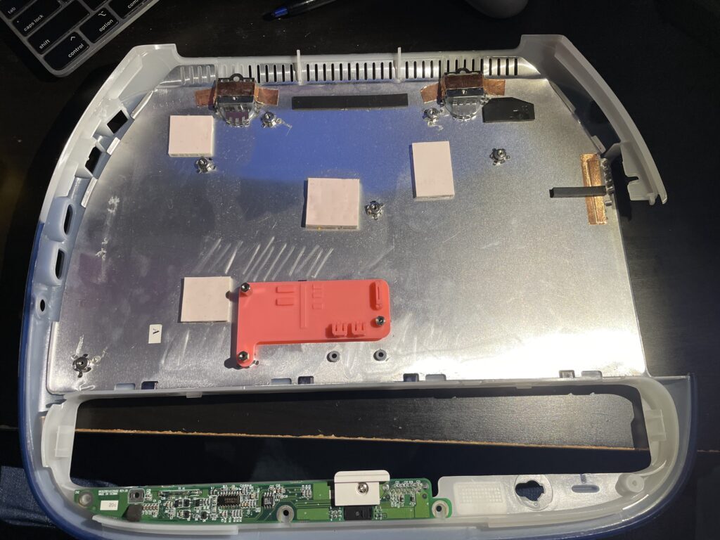
I had initially thought about making a board to replace the “battery board”. The thing that pushed me off of this is that the button is already in place and it’s easy enough to solder on to the existing contacts. I doubt I’ll use any of the actual battery connector features as actual iBook batteries are hard to come by.
The Lid-closed sensor is a guess. There’s a little glass capsule on the board that has two metal contacts in it. These are referred to as Reed Switches. When you bring a magnet near it, it’s supposed to push the contacts together and complete a circuit. In mine, the contacts are already together – and as far as I can tell a normally-closed Reed Switch is not a thing. I think I can get away with replacing it and just soldering wires to the contacts. If that doesn’t work, I can probably hack in a hall-effect sensor and get the same behavior.
Version 1
As noted in my trackpad explorations, I was hoping to change modes of the trackpad and get some improved features. I didn’t want to marr my current top-case, and reached out to Billy Hughes to see if he had one he was willing to part with. Billy became semi-famous a couple of years ago when he started modifying iBooks into iPad dock/folios. His design incorporated a 3D-printed top-case, and a 3rd-party keyboard and trackpad. I asked him if he had any interest in a board that could adapt the original keyboard and trackpad and he was quite enthusiastic.
So now I wasn’t designing a board just for myself. but one that would accommodate some different needs. Namely the one for an iPad dock would need its own microcontroller. The easy solution I had was to simply provide a footprint for a Raspberry Pi Pico.
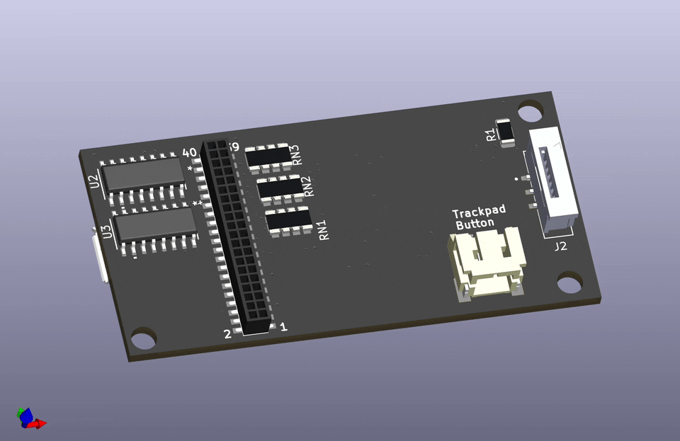
This version didn’t have connectors for the lid switch or the power button. Furthermore, the mounting holes didn’t line up to anything in the iBook chassis. One of the ideas that I’ve had is to 3D print something that mounts on the chassis, and then put everything I make on that, such that I don’t have to stick to Apple’s mount choices.
Version 2
I wanted to support the previously mentioned lid switch, and power button. I also wanted to host a connector that would plug into my own RP500’s keyboard port. Initially I planned for this to breakout to a ribbon cable, but I realized that I would be converting things more than necessary. So I went with a Flat Flexible Cable connector and will just route a longer FFC between the two.
Because the version I need for my one-off project, I also implemented a 2-pin external power. The 26-pin FFC coming off the RP500 is just for a matrix keyboard, and doesn’t have any power or ground lines. I figure I can just find a pad providing a reliably 3v3 signal and tap on that.

That leaves the ambiguous RGB connector listed here. About 18 months ago a hardware engineer going to the handle Smashcat teased a keyboard underlight for their iBook project. It very cleverly aligned LEDs below the keyboard going through the key-hinge mount points. The metal base of the keyboard was pushed in a stamp to provide points for the keys to mount. SmashCat designed a PCB that lays out the LEDs under these holes, along with driving hardware. Very cool stuff. I didn’t think I was up for the multiplexing associated with the project, but when I was at Supercon this last year I was gifted a Skull of Fate SAO – which had extremely small RGB LEDs as the eyes.
The XL-1010RGBC-WS2812B is a 1.0mm x 1.0mm version of the very popular WS2812b “neopixel”. It’s a great little LED and can be driven in serial with just a VCC, Ground and data pin. It’s about 150 LEDs, but I’ve got a strip of 300 WS2812bs around my window being driven by an ESP8266. The RP2040 shouldn’t have any trouble driving them.
I decided that the RGB lights were going to be a stretch goal for the project. I’m excited about the notion, but I want a working Laptop.
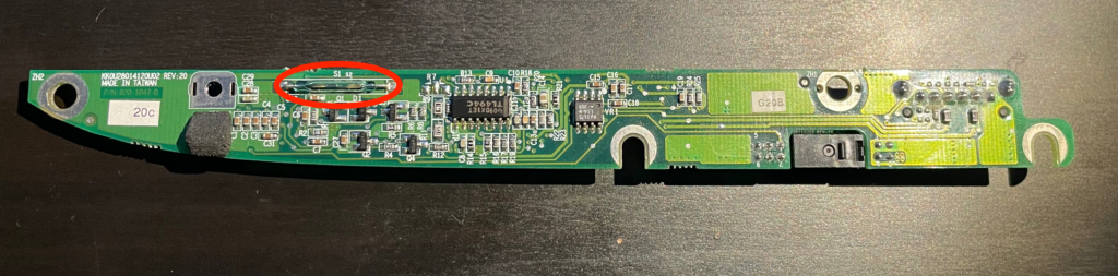
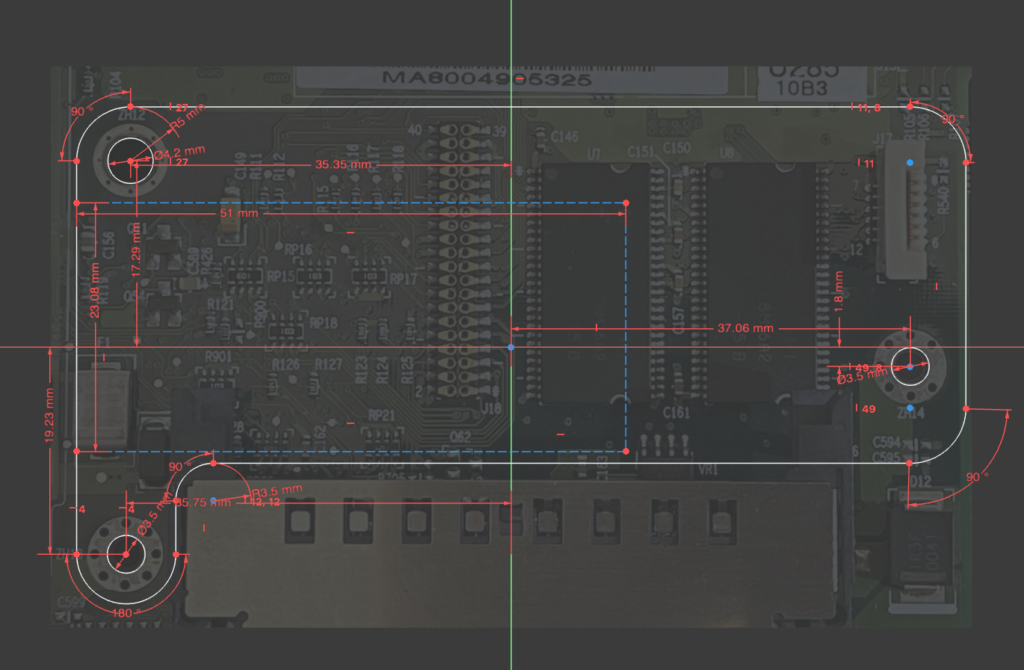
Board Reference
Because of the placement of the connectors, and the positions for mounting screws, I needed a reference to work against. I took an overhead picture of the part of the logic board that I needed and pulled that into KiCAD with the Add Reference Image feature. This helped placing the Keyboard and trackpad connector.
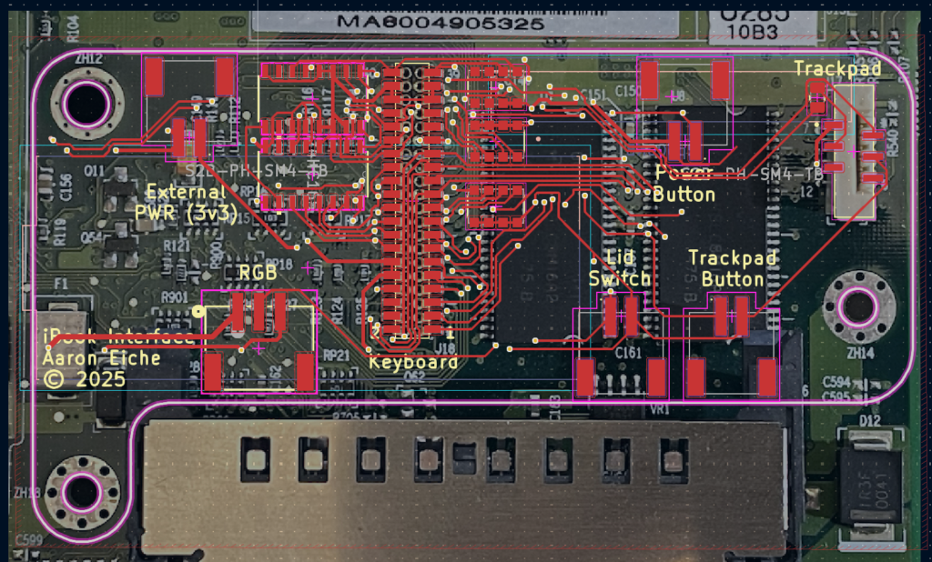
The board outline was trickier. After several failed attempts trying to use KiCAD’s drawing tools to get the shape I wanted, I switched over to FreeCAD. The tools are quite a bit more flexible and have a lot of features that make drawing shapes you want easier.
Further work
Something that I’m still thinking about doing is ditching the Pico in favor of laying out the RP2040 and support components on the board directly. I would prefer a USB-C connector over the Micro-USB on the Pico, and I would have the power supply onboard for my RP500 version. For the moment I’m going to put that aside, because my current goal is to complete the project.
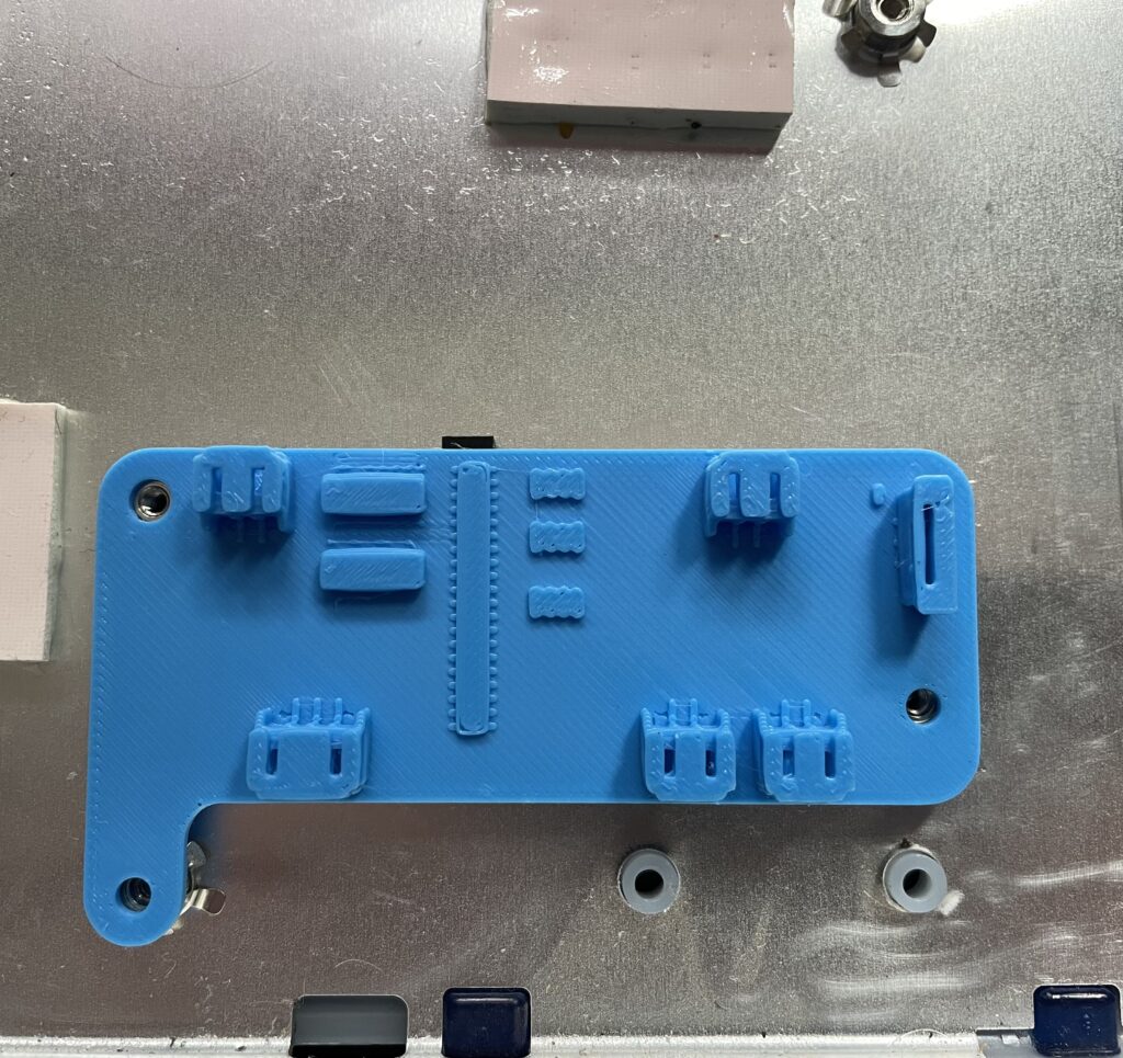
Test Fit
Having a solid design, I wanted to test the fit before I sent off to China for the boards. I started doing this once I had a 3D Printer that could reliably print representations of my board. I’ve found it to be really nice to hold the board in my hand. Make sure it feels right, and see if it fits where I want it to.
Next Steps
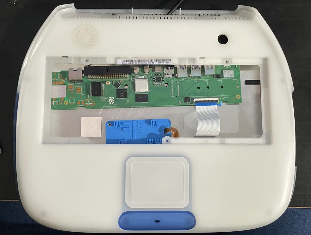
There may be another iteration of the interface board before its finalized. I think at the very least I’m going to move the connector for my version to the right hand side. Seeing it in place it’s obvious that’s the most convenient place to connect.
I don’t want to try to do too much with this board. At the end of the day, it’s purpose is to interface with the stock input components of the iBook.