iBook keyboard reverse engineering
When I started this project, I really only had a vague idea of how modern keyboards worked. There were a few people who had done some work on the iBook keyboard, but not a lot of information about it was done.
The iBook keyboard has a male 2×20 pin connector, with a 1.27mm pitch. It turns out that this arrangement is not currently very popular, and I was having trouble finding a compatible part. Furthermore no one seemed to have a definitive reference for the pinout.
I went off pictures, and a few references across the internet. The most useful of which came from Dr. Francintosh, who has been documenting his own efforts to replace the innards of an iBook with a modern Apple Silicon
How the iBook’s Keyboard works
The iBook’s keyboard follows the same conventions as other laptop keyboards, but also has some unique(?) features.
Most keyboards have a little microcontroller inside them that takes the input data that its supplied and sends it to the computer in a convenient form. That microcontroller needs a way to figure out which keys were pressed. You could have an input pin for every key, but that gets challenging very quickly. Even microcontrollers with an abundance of GPIO pins top out at 30 or 40. A small keyboard like the one on the iBook has more than 70 keys.
To make it easier to gather all the keys’ states, we use a technique of combining columns and rows. As a simplistic example, imagine The first couple of rows of a keyboard – the number row and the QWER row.
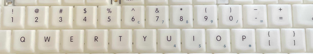
You can draw a line that goes through all the numbers, and another line that goes through the letters. These are your rows. Now draw a line that goes between 1 and Q, and another between 2 and W, and so on. These are your columns. You get something like this:
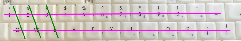
If you want to know if a key is pressed you send a signal from the row and listen for it at the column. You do it in sequence, checking every column and every row very fast, and by doing so, you can determine which keys are pressed.
I used a simple python program to iterate through a set of rows and columns to figure out which were what. After painstaking efforts of trial and error, here’s the full keyboard map that I came up with:
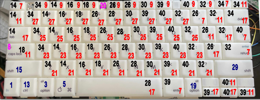
- The red numbers are the rows
- The black numbers are the columns
- The blue numbers are meta keys
- The magenta numbers are LEDs.
The numbers correlate with the 40-pin connector. Here’s a schematic for the female side of the connector:
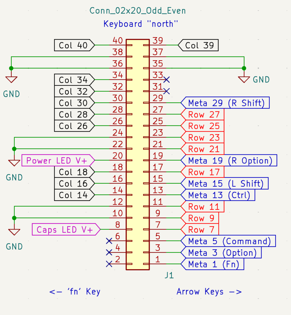
The blue meta keys are somewhat peculiar. Instead of being a correlated set of a row and a column, these keys use individual GPIO pins. It’s a little more “expensive” to have a single pin dedicated to a single key, but it’s advantageous to be able to read these keys outside the normal loop.
The Magenta pins are LEDs. Setting the pins as outputs on your microcontroller and pushing them high will send current through the pin and turn the LED on. One as a caps lock is as needed, whereas the other – a power indicator – presumably was always on.
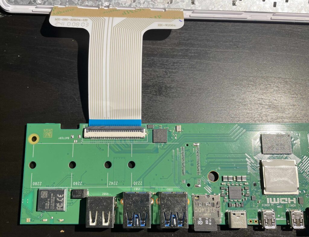
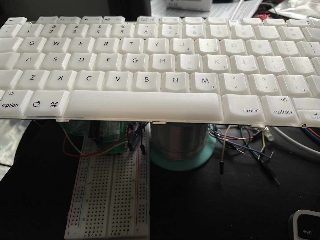
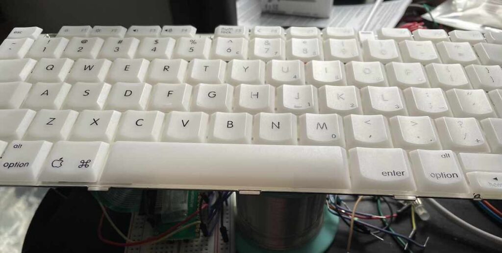
The iBook keyboard uses an FFC (Flat flex cable) but is terminated as a DIP pin header. The Raspberry Pi 500 that I’m placing in the iBook chassis uses just a flat cable into a flat connector. The chip just to the right of the cable in the image here is an RP2040 – the same chip that I’m using in my test efforts with the keyboard (though mine is on a Raspberry Pi Pico.)
Ideally, I would like to interface with this RP2040 and use for the keyboard and trackpad. I will have to design an appropriate adapter to go between the iBook’s connector and the RP2040. I will likely be including a shift register to reduce the number of GPIOs that I need on the chip. That way I can also handle the keyboard LEDs, and hopefully interface the trackpad as well. Fortunately, I have a codebase to rely on for the existing RasPi 500 keyboard.