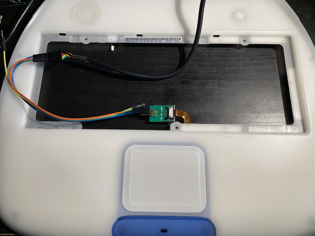
The Trackpad on the iBook is kind of obnoxiously inaccessible. The reverse side of the plate where the trackpad is housed is covered by a thin, solid sheet of metal. I assume the intent was to shield it from RF radiation. The shield is held in place by plastic knobs that have been heat deformed into a retaining shape. I could pull it off, but I’m not confident that I could satisfactorily put it back on.
As a quick aside, Apple is frequently, deservedly, called out for making their computers challenging to repair. The claim is often that the decisions are money-driven. While I don’t think that take is wrong, I also think that the primary driving factor (especially in the Jony Ive design-era) was manufacturing for form. That included the form of manufacturing processes. I think at least some of the design concept here was “It’d be cool if we could do it without screws!”
Anyway. It’s fortunate that I don’t have to tear it apart. Greg Smith – another iBook hacker – disassembled the iBook plate and shared his findings.
This let me move ahead to the software side of this. I had 3 goals:
- Get wiring right and see data coming off the trackpad.
- Read the data using circuit python
- Read the data using KMK (the keyboard firmware) to drive as a mouse
Hardware wiring
A few folks have tackled this issue before, including Greg (mentioned above) as well as a couple of folks in this Reddit thread. The pinout can be challenging. For future reference, here is a picture of the connector on the iBook logic board with the pins identified:
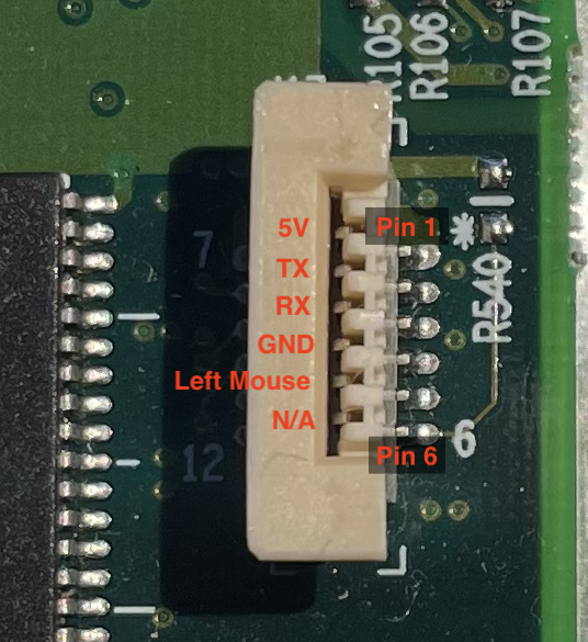
Pin 6 apparently doesn’t do anything, but if you look at the trace on the board here, it looks like the intention was to put a pull-down resistor on it. My guess is that it’s an unconnected support for the Trackpad’s Right mouse button – something that Apple didn’t use in this era.
I had trouble parsing the different interpretations of the pinout from various sources. As lazd pointed out, he hooked up his trackpad and it started getting very hot! I experienced the same thing. After a couple of failed attempts, I got out my multimeter and tracked down the GND pin, and followed other’s pinouts from there. Unlike others, I found it was easier to simply not plug in the TX pin. You can interact with the Trackpad, but as far as I can tell, the settings on this one are not adjustable.
Basic UART tests
It took a couple of false starts here too. After the trackpad started to heat up I was worried I had destroyed it. Fortunately I didn’t. Once I had the pinout correct, I wired it into my FTDI Cable and connected to it with CoolTerm. The output looked exactly like others pointed out. 5 bytes. One for Touch Start or Touch End. The next 4 bytes are (I believe) X Direction, Y Direction, X Relative Difference, and Y Relative Difference
I proceeded to see if I could get it to interpret the data properly in a circuitPython environment in preparation for moving it into the same environment as the keyboard. As I’ve mentioned previously, the keyboard will be ideally driven from the onboard Pico. If I can have the mouse handled from that as well I can leave open a USB port and not deal with an additional piece of hardware.
Synaptics Touchpad
Before I get any further, it feels important to me to mention the Synapitcs Touchpad Interface Guide. The touchpad that we’re dealing with was manufactured by Synpatics – which makes a lot of touchpads across computing to this day. This guide is available from an old Instructables article about recycling laptop touchpads.
The guide has a lot to say about the setup and usages of the touchpad. Reading it implies that this touchpad is a Serial TTL version, and the default mode is not the only one available. Specifically there are some really appealing data available in Absolute Mode. Data such as the amount of touch force applied, and how many fingers are on the pad.
According to the guide, there is a command interface to switch modes. I have attempted to access the command interface without any success. Digging deep, the guide says this:
the host must hold both DTR and RTS positive whenever it transmits command bytes to the
device. – Synaptics Touch Interface Guide – 4.3, pg 54
Eagle-eyed readers may notice that the RTS and DTR pins (common on serial connectors) are not exposed on the 6-pin FFC cable that Apple gave us. It’s reasonable to assume that the pins exist on the PCB, or at least the TM1004 controller chip – but that requires going through the RF shield, which I’m not willing to do at the moment. As near as I can tell Apple chose to implement the touchpad without allowing for the command set at any point.
ADB
There are some claims on the web that suggest that the Trackpad and keyboard in PowerBooks and iBooks are ADB. The Synaptics Touchpad Guide explicitly states that some of their products from this era had an ADB interface. At first I thought “Oh! Maybe I can access the features of the trackpad through that interface.” However, I think that the keyboard and trackpad are ADB at a higher level. That is, I think there are some electronics that are buffering the data from the keyboard and trackpad and providing that data to the rest of the system via an ADB interface. This makes sense as MacOS (both classic and OS X) had well-established drivers for ADB, and the keyboard’s electronics are not on the keyboard module – they’re somewhere on the logic board.
Drunken Mouse
I wrote a couple of trial and error scripts, and I’ve mostly settled on a working model. I was noticing some very weird jerky behavior when I realized that my logic was off. The data coming from the trackpad is in “relative mode”, where the change is described as positive or negative values relative to the previous location. In practice this usually means a +1 or -1 on either X or Y axis’. However if you’re moving really fast, you can get a 2 or 3 out of the data. I hadn’t accounted for these so I was getting a very weird, drunken-sort of mouse.
Probably the biggest challenge of the trackpad is its size. The functional space of the trackpad is 62mm x 46mm. Compared to todays trackpads, it’s shockingly small. For context, the trackpad on my work-supplied 2020 MacBook Pro is 160x100mm: Nearly 2.5x the width and height. I think the current Mac Trackpads are much too big. My 2014 MacBook Pro is 100×76, which feels about the perfect size. At any rate, the iBook Touchpad is small. As a result, you have to do some pretty fancy acceleration or find yourself dragging in far too many small increments.
Once I got a reasonably-working firmware running, I brought the code and the trackpad back over to the module I’d wired up for the keyboard, and plugged it in.
New Problem, who dis?
With everything running on a single Pi Pico module, I was running into a new problem that I hadn’t really seen previously. If I went too fast and tried to do too much with the trackpad, the mouse would freeze up. More specifically, it would simply stop responding.
I thought I might be taxing the processor, but this is not the 8-bit ATMega168 you might find on keyboard projects from a few years ago. The chip on the Pi Pico is a 150Mhz 32-bit ARM Core-M0. Even being lazy about my code I wasn’t going to be pushing it with what I was doing.
The problem turned out to be in how I was reading in the data from the trackpad. With KMK, everything is centered around keyboard scanning.
def before_matrix_scan(self, keyboard):
        if self.uart.in_waiting:
            data = self.uart.read(5)

            if data[0] == 132:
                dy = self.generateMove(data[1],data[3])
                dx = self.generateMove(data[2],data[4])

                AX.X.move(keyboard, dx * 10)
                AX.Y.move(keyboard, dy * 10)
The basic explanation here: If there’s data coming in from the Trackpad (UART), read 5-bytes. If the first byte is a “touch down” indication, generate the x and y changes, and then send them to the computer. The problem is that I would read 5 bytes, and move the mouse. If the trackpad was generating more data than I was parsing, the buffer would just fill up. And it would have to wait until it was all emptied.
The fix is to pull down the data from the buffer as soon as you can, and process it all. This happens exceptionally fast (again, 150Mhz: One-hundred and Fifty Million instructions per second). We should have plenty of time to handle the trackpad, and the keyboard.
Next Steps
Now that I have a working version of the Keyboard and the Touchpad, I need to write an acceleration function for the trackpad. Right now it’s just multiplying the change by 10 and it needs a little more finesse to come out smoothly. I am also awaiting a spare trackpad setup to see if I can access the required DTR and RTS pins to get it to accept commands.
Onward and upward!