My parts for the Star Sensor arrived today, 4 days earlier than anticipated. I abandoned everything else and spent the next couple of hours figuring out how to assemble my first StarSensor SAO.
When I ordered these boards, I neglected to include a stencil with them. This was in-part because of the board house mixup. At any rate, I had to hand-apply solder paste. In the past I’ve done this with a syringe and a lot of patience. However I recently came across a video talking about applying solder paste by hand and found to be pretty useful. It comes down to mixing in some flux, and then using a very small piece of wire (in my case the lead of a diode)
I applied it under a microscope (sadly I don’t have an adapter to show you pictures) and it turned out pretty well.
It was about this time that I realized I hadn’t ever figured out what resistors I needed for these boards. You may recall from last year’s MacSAO that early on I tested an exceptionally bright LED through the board, and I wanted this to look as nice authentic as I could make it.
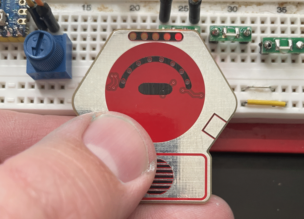
So I setup a sort of test-rig on a breadboard with the 3 LEDs and a trimpot. I placed one of my PCBs over the LED and kind felt-around for the right values. If you’ve not seen it before, this is the trick of shining the LED light through the PCB. It results in a decently diffused light and can be used to light up spaces nicely. The goal here was to light up the score indicators as bright as possible without the light bleeding over to the next dot too closely.
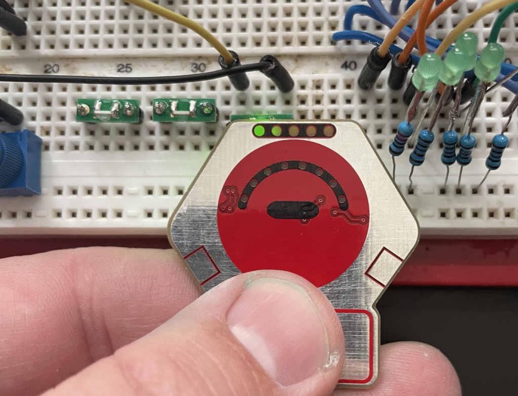
I didn’t have the appropriate 0603 sized resistors, so I turned to my resistor collection to see if I could find the correct values. But my resistor set is 0805 – a little too big, but not so big that it wouldn’t work. It’d just be a little crowded.
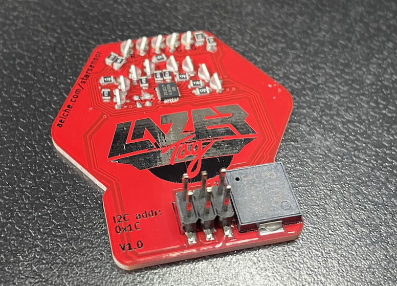
The reflow process was a bit rough. I used a hot plate and didn’t ramp up and down the heat properly, so it took a long time, and then after all the small components had reflowed, the buzzer and pin header hadn’t yet – so I had to leave it on.
I did see a sort of interesting phenomenon while I was reflowing, and that was gases vaporizing under the LED lenses:
Programming
A little worse for wear, I brought the complete prototype in and tried to program it. To my delight the programmer identified the chip correctly. This meant at least that the chip was put on correctly, was getting power, and responding to the programmer. This was a huge win as my track record is not great for first-time boards.
The programmer didn’t work perfectly though. For some reason, it hung when trying to write the firmware. I double checked the connections, but didn’t need to. I already had evidence that the communication was working. I put the board under the microscope to take another look. There were a couple of places that felt a little messy, but nothing stood out. All the pins on the microcontroller were clean.
Eventually I decided to see if my Gameboy SAO firmware would load. They had the same chip, same programmer. A good way to test if it was a the hardware or the software. And it worked. Virtually nothing turned on, because there wasn’t a screen. So I tried the “blink” example in the CH32V003Fun library. That also worked.
Then, I copied the code for the StarSensorSAO over to the directory where the examples were. And that compiled and flashed! So I have no idea why it didn’t work in the original directory. And I might chase it down at some point. In the mean time, I have a StarSensor!
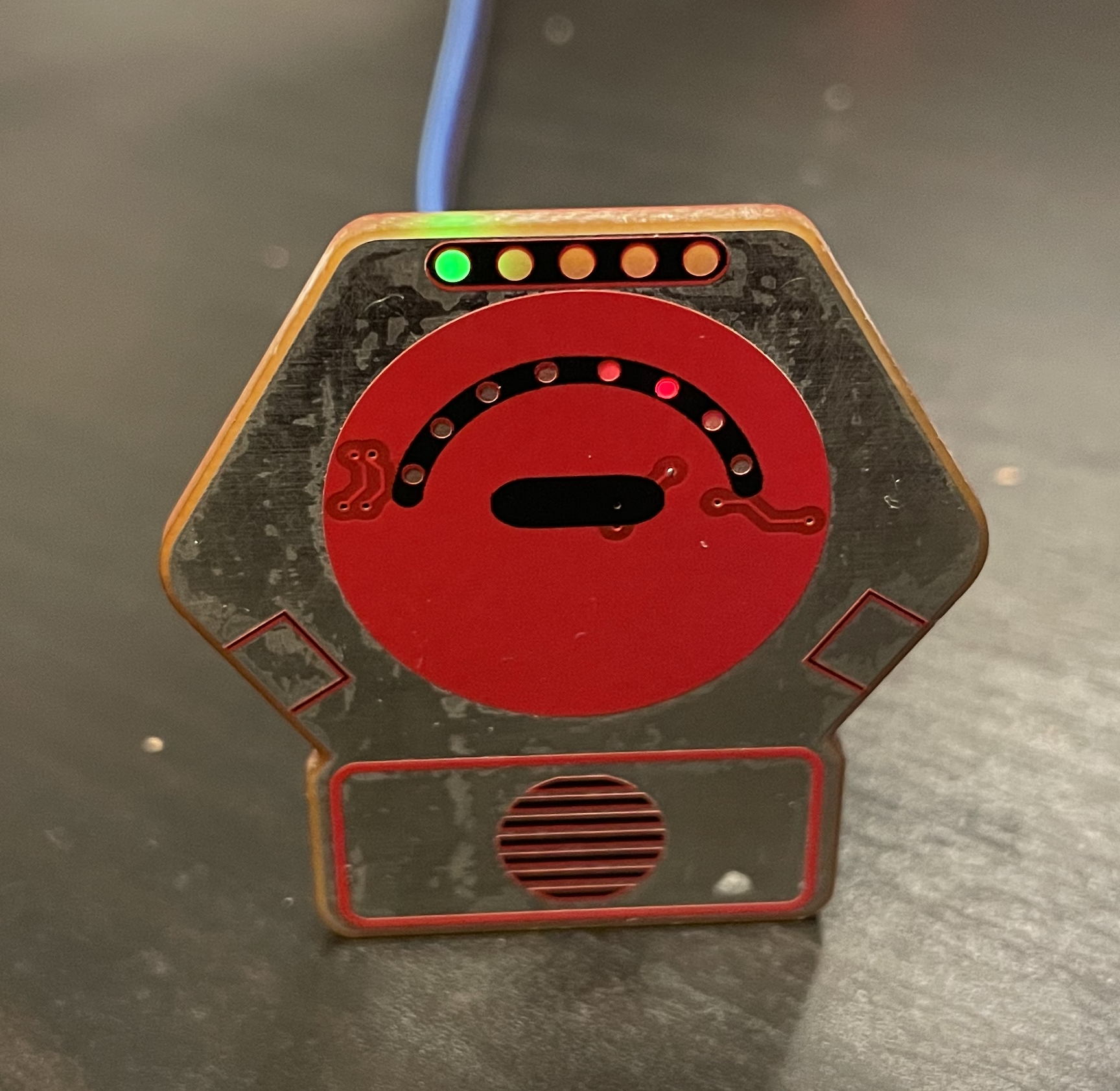
At first I thought that the light-bleed from the “scanner” part of the device was going to annoy me, but it turns out to be a happy accident. The light bleed means that that the adjacent LEDs appear lit-up a little as well. That better matches the behavior of a larson-scanner than the outright on-off nature.
One amusing behavior
There were immediately a few things to fix. The scanner lit up inverted, meaning that the tracer was “off” while the other leds were on. Also, I kept seeing this weird flashing behavior on the score section – and it very clearing was doing binary counting.
Then, I observed that it only occurred when I was touching it. It’s a bug not a feature – my SAO is a capacitive button! I did not expect that, and I’m not clear how it’s working. It’s possible that it’s firing on the i2c pins. At any rate, it’s kind of a funny thing to see. I’d love to be able to work it into the functionality, but we’ll have to see how it goes.
So I’ve got a working board! Next up is a stencil, assembly, and oh yeah – I need to write some firmware!