 That is to say, my first PCB that I actually designed. I recently began attending a bi-weekly electronics hobbiest group call Dorkbot PDX. It’s basically an opportunity for nerds to show off their random electronics projects to people who might actually be interested.
Anyway, the group also does a monthly PCB order. You make your design, send it off to Laen, who manages all this, and he sends it off to a PCB fab house out in Colorado. This all for $5/square inch and you get 3 of your design.
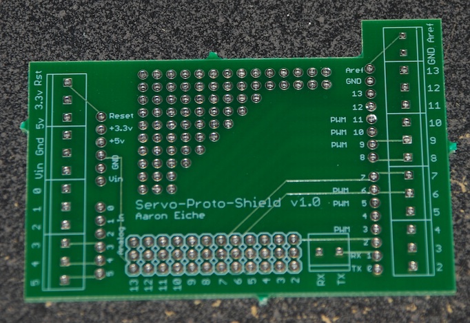
I’d been toying with the idea of an Arduino shield that mixes the best parts of the prototyping shields I’ve seen. I also wanted a board that I could plug several servos into for servo control. What I ended up with was the “Arduino Servo-Proto-Shield”. You may have seen the rendered version in my last post.
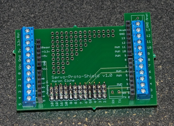
The shield breaks out all of the 28 pins into 3.5mm screw terminal blocks. It also has long-tail female headers for additional shield mounting. The 12 digital pins (2 through 13) are broken out into Servo-motor headers. For fun I threw in some 0.1″ vias if I want to add some permanent circuit.
Unfortunately, I made one minor mistake in my design. My 2-terminal blocks had the wrong drill size set for the hole, as a result, they’re just a bit too small to accomadate the terminal blocks. So unfortunately the breakout for my GND, Aref, and Serial communication is out of commission until I find a way to shave down the posts on the terminal blocks.
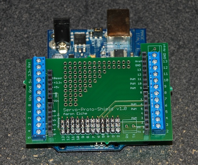
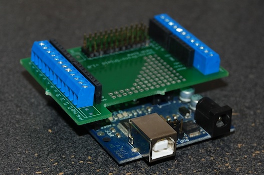
I soldered it this evening and plugged it into my Arduino. It looks good, and I’ve tested all the connections – they all work fine. I just have to make this do something now! Any of you who read this and have an interest: What do you think could be improved? I’m looking for ideas and thoughts to make this a better shield.
blinking lights — everything should have blinking lights.
Seriously, I have been thing about a shield for servos. This is a good design.
You might want to make the reset button easier to get at, or add a reset button to the shield that connects to the arduino.
I like that design over the wing shield. Seems like the wing shield puts all the stress on the pins while yours distributes it. Ever think of selling that one as a kit?
-d